T5 Lightning, PTR-175 radio & intercom system test set / simulator
NOTE: A seperate page on the tech side of the PTR-175 here.
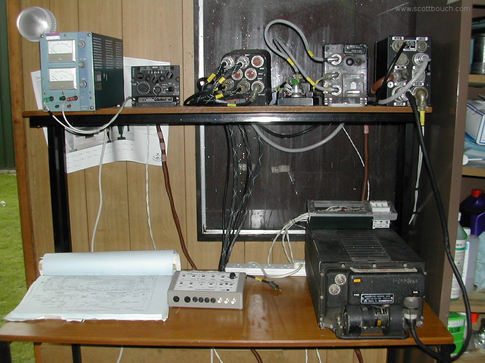
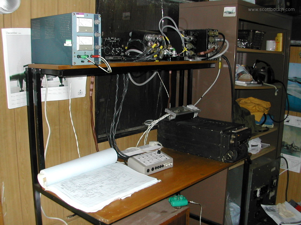
I built this test set back in 2005 along side Rod Barker.
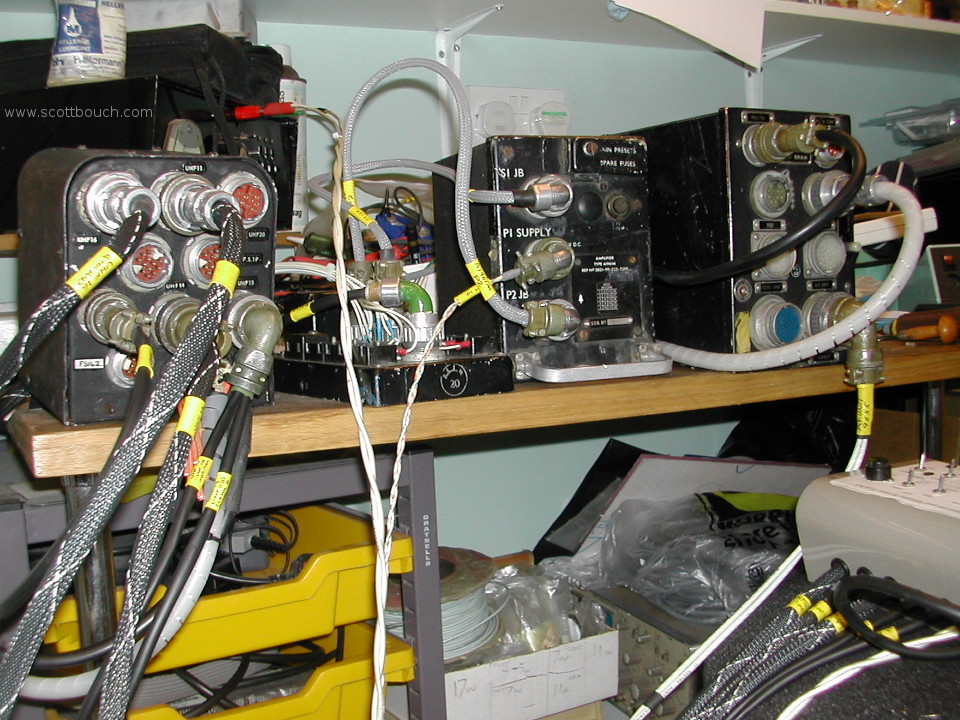
It was useful in diagnosing faults with T5 Lightning XS458's radio system, as it allowed parts of the system to be pulled from the aircraft and bench tested, out of the wind and rain.
The test set is pretty much a replica of the aircraft wiring, all harnesses were made to connect each box together as they are connected in a real T5 Lightning.
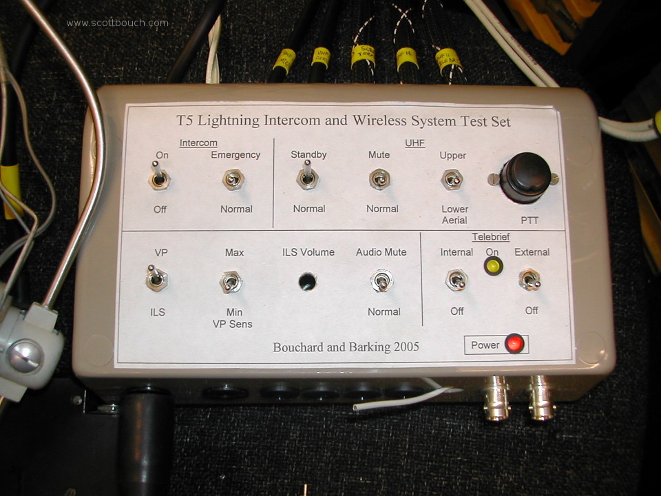
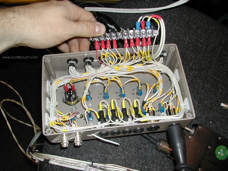
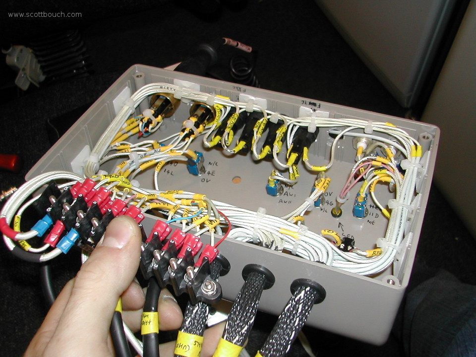
We added the plastic switch box to allow for cockpit mounted switches that are additional to the main PTR-175 Control Unit. the box also gave us a location to add the fuses for the system, exactly as per the aircraft wiring.
Most connectors are Plessey Mk4 (and some green Mk7), which meant a lot of fiddly work in building them up with the correct configurations. Luckily at the time we had access to some of the correct original Plessey Mk4 spanners / tooling for the job.
The video below indicates why it's useful to have a BENCH test set!
Public display
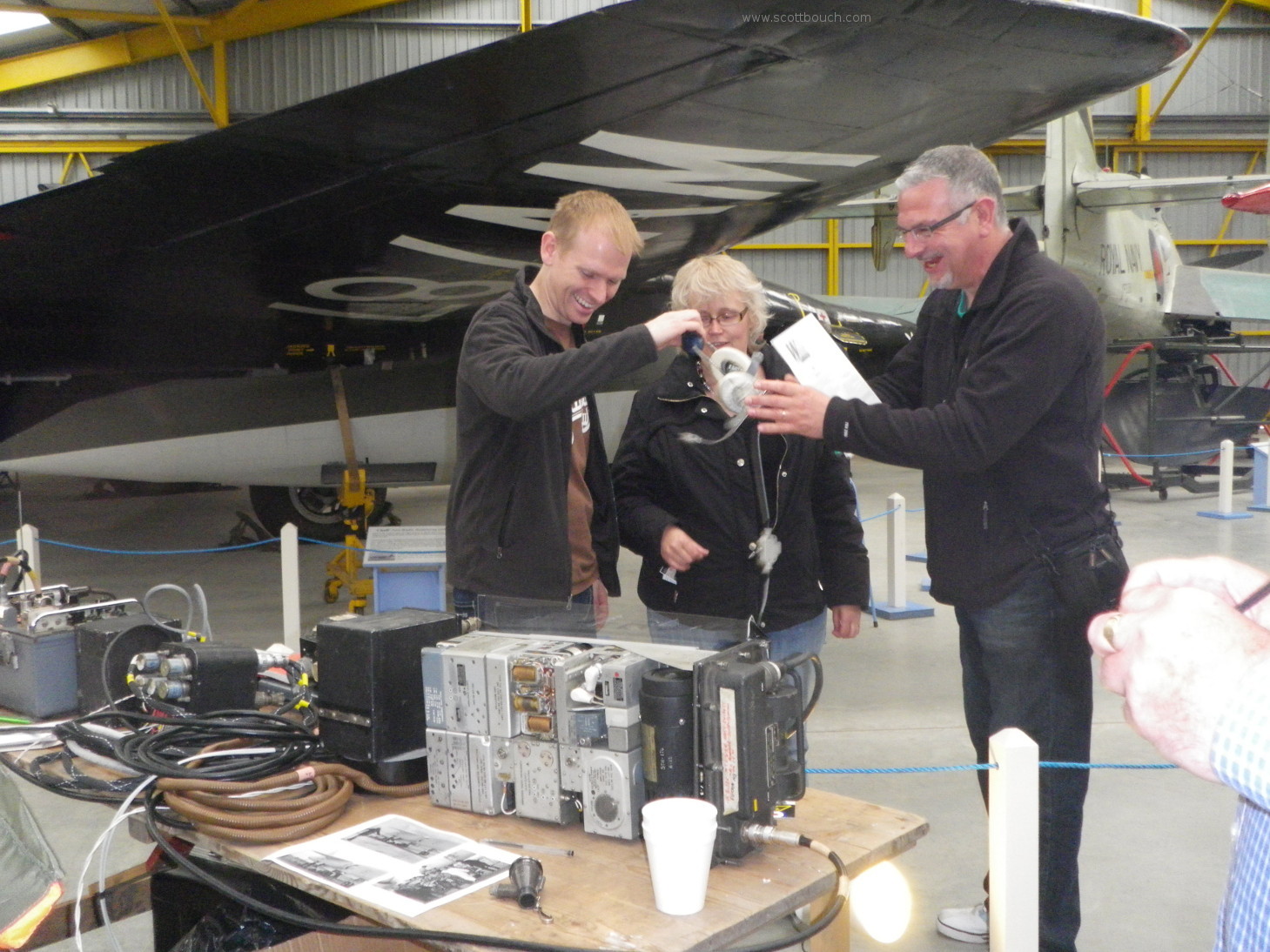
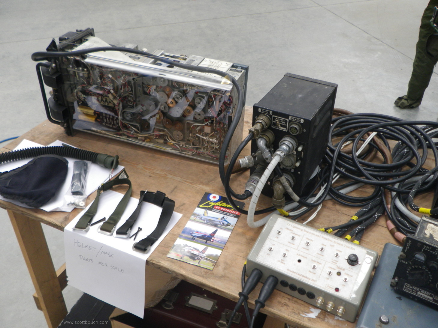
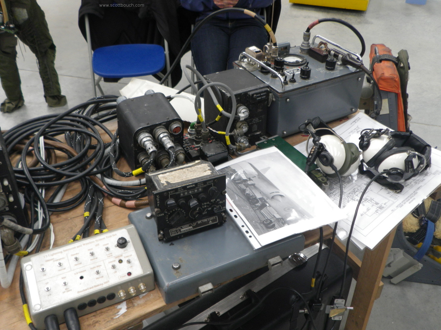
The following images show the set on public display at Newark Air Museum's 2010 CockpitFest event:
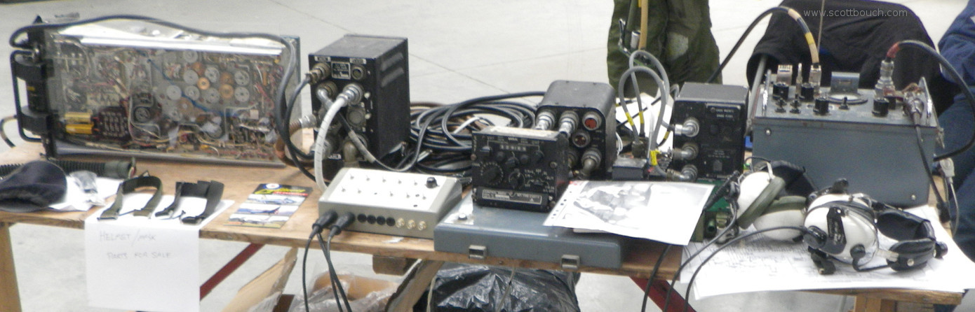
People liked wearing the headset and hearing exactly the sounds that a 60's fighter jet pilot would have heard through his helmet headset.
Look closely at the PTR-175 radio TR unit, it's half mechanical! The stainless steel and phosphor bronze gears select different crystals, and re-tune variable capacitors when the pilot selects different frequencies from the cockpit. Real vintage technology!