EE Lightning T5 Technical Resource
- T5 Cockpit
A look around the cockpit of T5 Lightning XS458. Jump down to the T5 Virtual Cockpit Tour.
A general look at the instrument panel:
Starting with the rear bulkhead and Martin Baker Mk4BSC ejection Seats and then the instrument panel:
Tips:
- Red fibre glass cockpit sill guards are in place protect the infaltable pressure seal from damage.
- Left seat PEC is not fitted, cover is in place.
- Seat pads were brown leather for the Lightning, alterative pads and carpets used to save wear of originals.
- White bag hanging from Port stick brake lever is not original.
- Video camera tripod head mounting between seats is not original.
- Grey box clipped to Starboard seat webbing up high is a unit I made to allow the video camera to record the R/T, so is not original.
Moving the flying controls, a look at the rudder pedal mechanism, and behind the instrument panel:
Now with battery power ON, warning panel lights illuminated, and red attention getters flashing, pressing the "C" Cancel button stops the flashing, and also stops the "Clangers" (audible warning) in the headsets:
A look at the Martin Baker Mk4BSC ejection Seats, and the cockpit side consoles, ending up with a little look at the squadron graffiti to be found in the rear bulkhead first aid box.
Tips:
- Red fibre glass cockpit sill guards are in place protect the infaltable pressure seal from damage.
- Left seat PEC is not fitted, cover is in place, and Right seat PEC is wrong type, is for a Buccaneer and Sea Vixen.
- Seat pads were brown leather for the Lightning, alterative pads and carpets used to save wear of originals.
Sounds of the cockpit
This video was taken during a high-speed taxi-run. The audio is a mix of exactly what the crew hear, and ambient cockpit sound.
More sounds of the cockpit
I made some accurate / detailed headset audio recordings in 2018 using T5 Lightning XS458, please see here: Audio Samples.
AWP and SWP Lamp Logic
This spreadhseet detials the logic behind the AWP and SWP indicator lamps under normal and fault conditions: Download
T5 Lightning Virtual Cockpit Tour
I've conducted countless cockpit tours of T5's XS452 and XS458 over the years to the public on airshow days, but thought I'd make it accessible to more people by creating this page!
Plenty of people have published photos online of cockpits, but I've tried to give a bit of a feel for what the cockpit equipment actually does, how it works, and how a human interacts with the different systems of the aircraft, adding in notes of interest here and there.
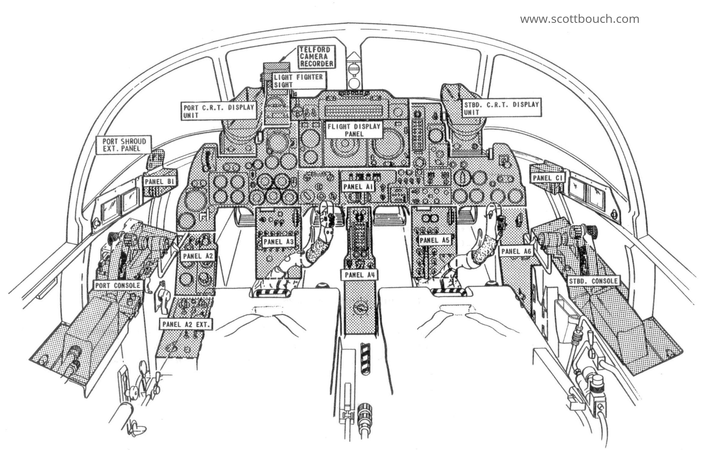
Overview
Instrument panels and main items of the T5 cockpit identified. The panel numbers relate to the following sections of this page.
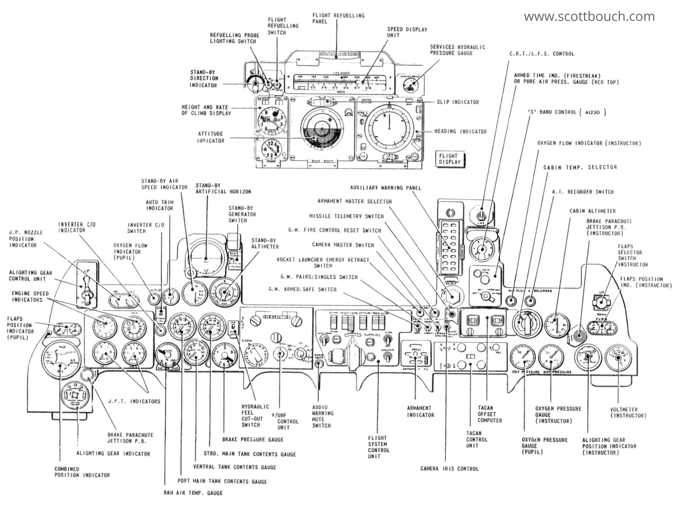
Panel A1 and IFIS Display
Main cockpit panel, home to engine and fuel indicators, main and standby flight information indicators.
The Flight Display Unit also known as the IFIS (Integrated Flight Information System) consists of: Indicated Air Speed Display; Height and Rate Of Climb Display; F4C Attitude Indicator; Navigation Display (displays Compass, ILS, Violet Picture or TACAN information).
The IFIS concept uses a central array of measuring instruments, such as pitot static pressure sensors, MRG (Master Reference Gyro), etc.. then the Flight Data Computer passes this information to the cockpit displays, but also makes it available to other systems too, such as the Flight Control System, weapons, etc... This system was a Cold-War era innovation, as previously independent aircraft instrumented systems used duplicated sensing elements. The IFIS also appears in the Gnat T Mk2, Hunter T Mk7A, Buccaneer S2B (and possibly other variants), certain Harrier variants, and possibly more airctarft.
The V/UHF Control Unit is a C1607/4 for the PTR-175 radio.
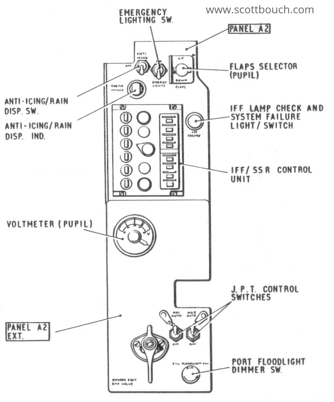
Panel A2 and A2 Ext
Location: to the left of the Pupil's left leg.
Home to the IFF/SSR (Indication Friend or Foe / Secondary Surveillance Radar) Control Unit, which identifies an aircraft as friendly or hostile by means of an interrogating ground radar. The Transponder is automatically switched to Emergency Mode upon either occupant ejecting.
The JPT control switches allow the pilot to override the engine's inbuilt Jet Pipe Temperature protection, allowing for extra power if needed at the expense of the mechanical integrity / longevity of the engine turbine and jet pipe due to thermal stress.
The unmarked handle at the bottom is the Pupil's Oxygen Shut Off valve.
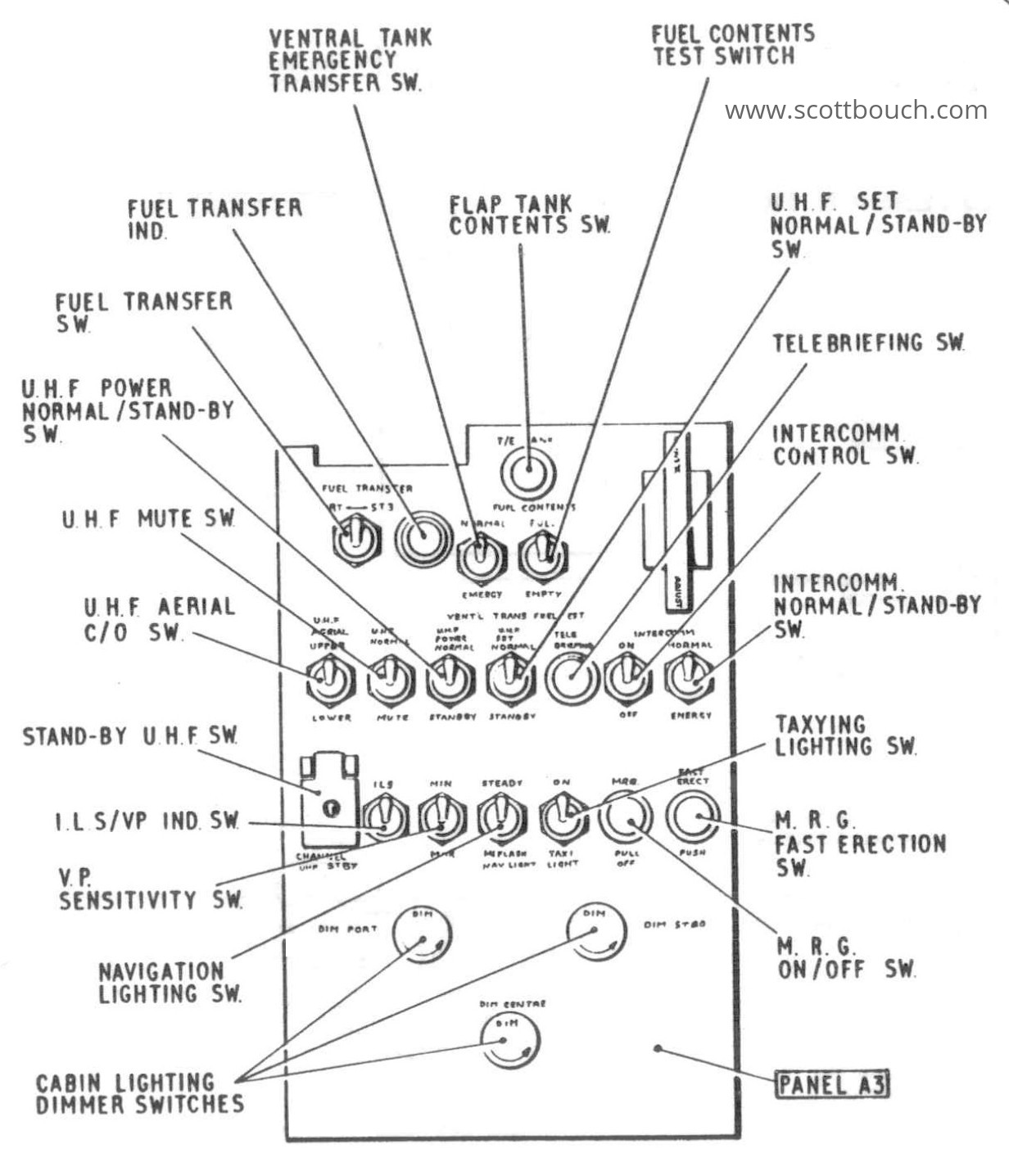
Panel A3
Location: between the Pupil's legs.
This panel includes switches controlling: Intercomm amplifier; VHF/UHF Radio; Telebrief; Internal and External Lighting; Navigation aids; Fuel Transfer between wings, and Fuel Contents Indicator Test.
The VP/ILS switch is an interesting one, as when in Violet Picture mode, and the radio switched to ADF (Automatic Direction Finding), the Navigation Display ILS Runway Localiser Indicator can be used to indicate the relative bearing of UHF radio transmissions, known as "Homing" - useful to find a Victor tanker if your TACAN has failed, or for locating a Russian Bear... The twin needle-like aerials on top of the Lightning spine are used for this purpose.
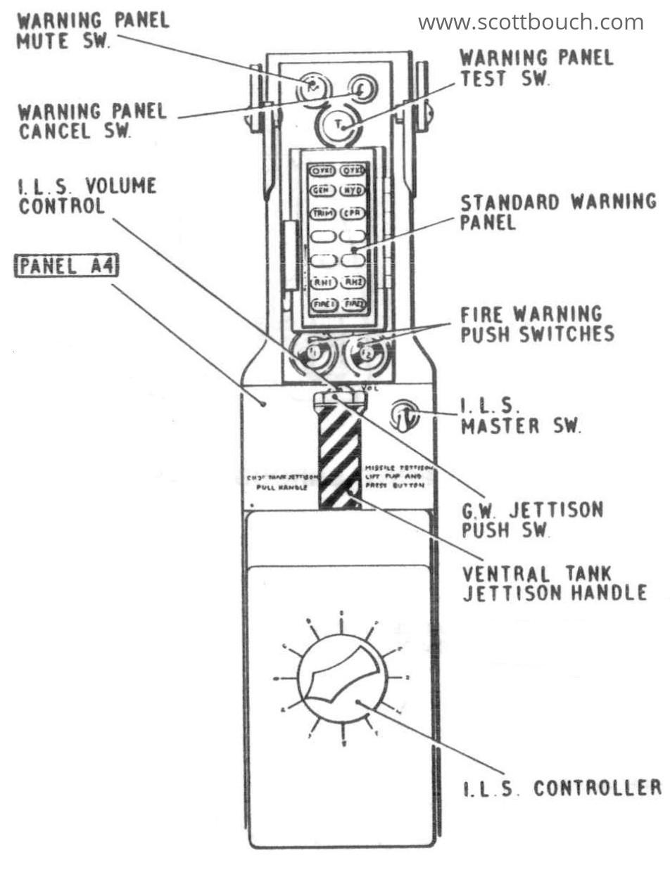
Panel A4
Location: between the Pupil's right and Instructor's left legs.
The ILS (Instrumented Landing System) controller can be set to a number of preset channels.
The Standard Warning Panel also includes fire warning indicators from the Graviner fire system, and controls for the extinguishers.
The Ventral Tank Jettison Handle also includes a push button to jettison the Firestreak or Red Top missiles under a secret flap in the top of the handle.
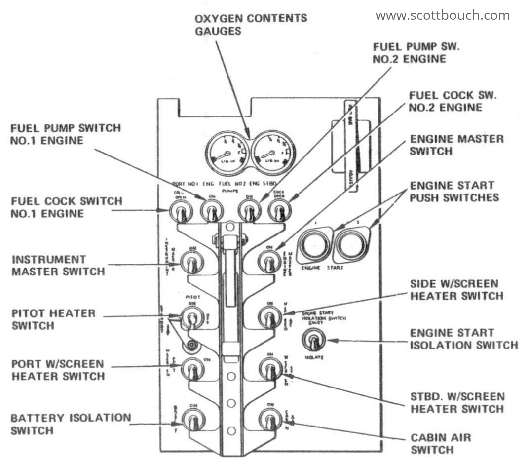
Panel A5
Location: between the Instructor's legs.
All engine starting, fuel control, and other essential switches are on Panel A5.
The ladder rack assembly has a central handle which when pulled up, slides the rack upwards, turning all essential switches on simultaneously with quite a thump! This was engineered to save time during a QRA (Quick Reaction Alert) where a Lightning could be airborne in about a minute, an essential aspect of a Cold-War interceptor aircraft.
The T5 carries Liquid Oxygen (LOX) cryogen in two dewars, which was boiled off into gaseous oxygen to supply the aircrew. These two indicators show how much liquid is left in the dewars by using a capacitive measurement system.
Panel A6
Location: to the right of the Instructor's right leg.
The AI changeover switch tells the Ferranti AI23D radar which controller is in control as the Pupil and Instructor have one controller each
The UHF Mute switch mutes reception of the PTR-175 radio, allowing peaceful conversation between Instructor and Pupil. The Instructor also has a UHF mute button on his control column.
The Instructor's Oxygen Shut Off valve handle has to have the end cut off, as it would clash with the side panel of the cockpit, so is a modified version of the Pupil's on panel A2 Ext.
Note: the Rudder Pedal Disengage lever was removed as a modification, I've never seen one still in place.

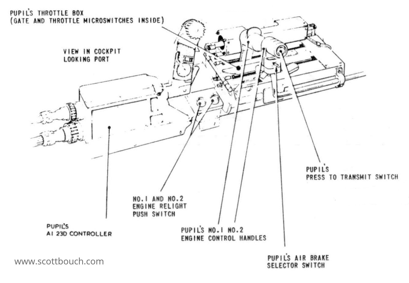
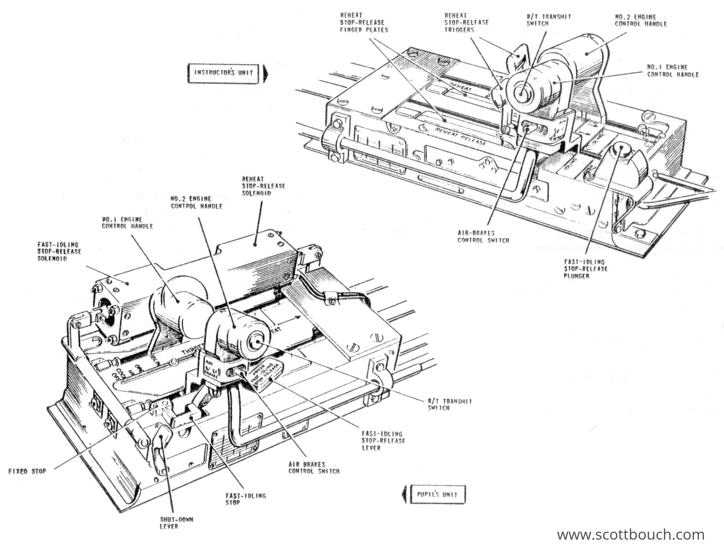
Port Console
The throttles are No1 to the port, and No2 to the starboard. The engines are No1 lower, No2 upper.
Reheat is controlled by sliding the throttles left through a gate and continuing to push forward. Two solenoids live inside the Pupil's throttle box to open this gate, these solenoids are controlled by switches on the Instructor's throttles, allowing the instructor to also be able to engage reheat.
NOTE: Fuel consumption of both engines on reheat is 14 gallons per second!
There is a small lever which stops the throttles being pulled right back, an action which stops the engines running. This lever has to actively be pressed to shut them down. There is a large rectangular solenoid on the port side of the box which activates this lever from a button on the Instructor's throttle box, so that either person can shut down the engines.
The relight buttons simply activate the engine ignitors, as in flight a flamed-out engine will rotate due to windmilling, this allows the engine to be re-started in flight.
The AI23D controller allows the Pupil to control the radar, which amongst other things includes locking on to targets, and using this information to automatically navigate the Lightning toward the target via the FCS, Flight Control System / Auto Pilot.
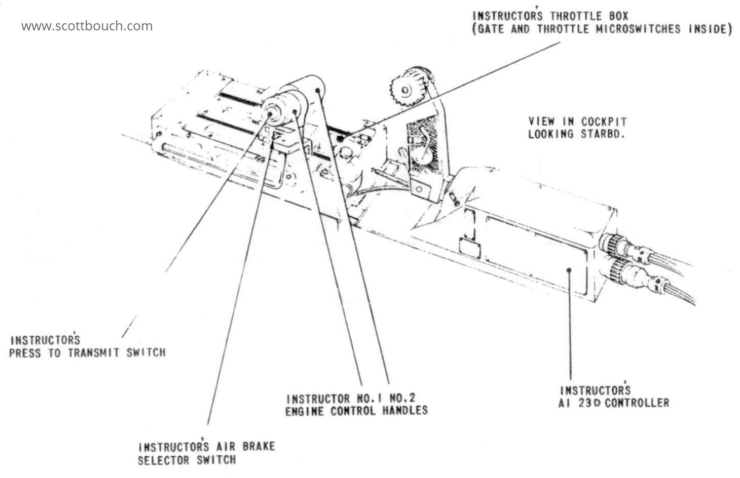
Starboard Console
Location: Instructor's right elbow and hand area.
Instructor's throttle box and AI23D radar controller.
Descriptions are as per above for Pupil, but this throttle box contains the switches to control the solenoids of the Pupil's throttle box.
These Instructor's right handed AI23D controllers are unique to the T5; the Student's left handed controller is the same as in the single seat aircraft, which is what they were training for.
Throttles
Location: on port and starboard consoles.
Controls on the Pupils throttles are as per the single seat aircraft, but they have been modified with two solenoids to allow the instructor to remotely knock the throttles left past the Reheat Gate, and also to remotely overcome the Fast Idle stop. These solenoids are controlled by switches installed on the instructors throttles.
Also mounted on the throttles are the Air Brake selector switches, and U/VHF Press To Transmit buttons.
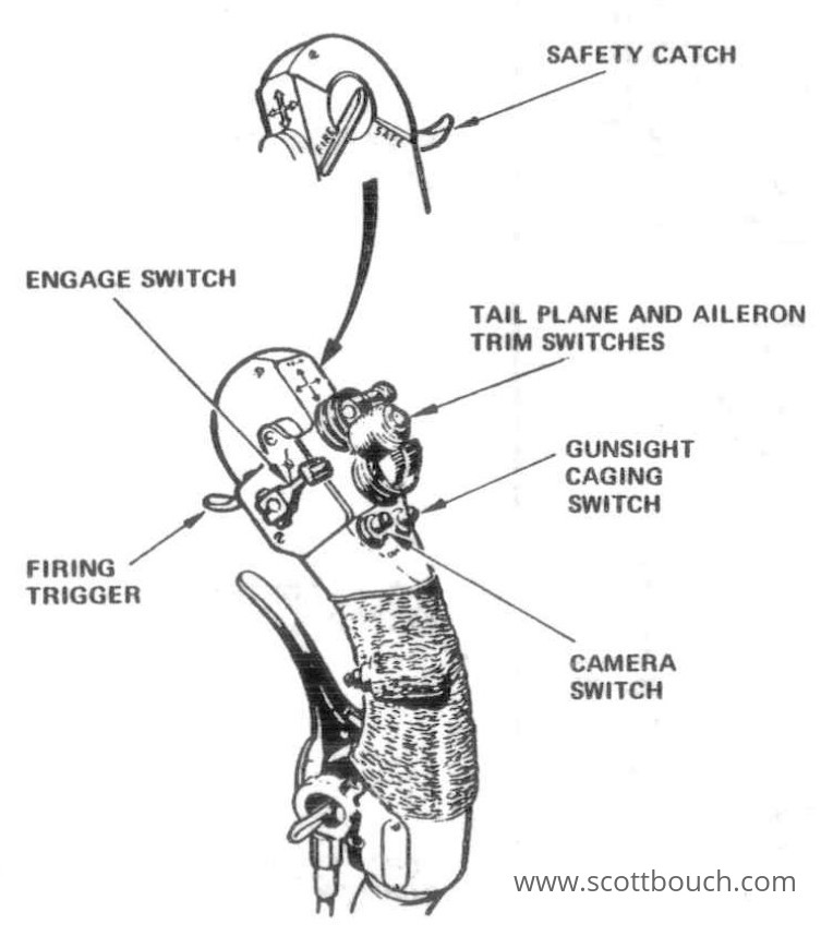
Port Control Column
The Pupil's port control column is identical to that of the single seat aircraft.
Pupil's control handle / stick includes brake lever for parking and differential braking steering. A small rotary lever low down locks the brakes on for parking.
The Camera button activates the G90 Gun Camera which is located in the air intake under the radar nose cone.
Also unmarked, next to the brake lever is a PTT, Press To Transmit button, which is connected to the PTR-175 radio, or standby radio.
The Engage switch has three positions: AP (Autopilot); FD (Flight Director); and Off. This switch sets the mode of operation of the Flight Control System.
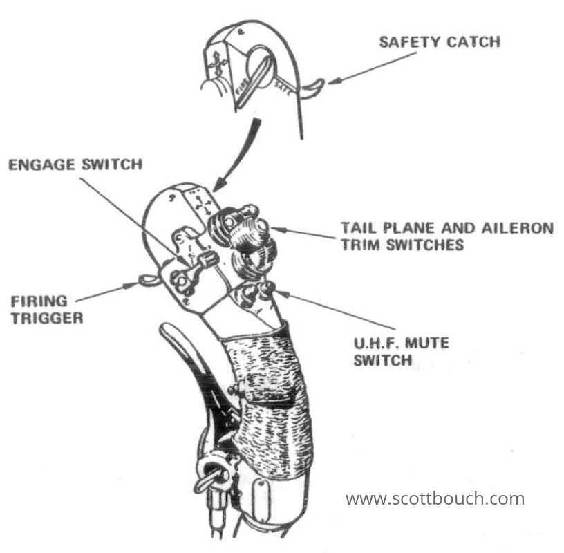
Starboard Control Column
Instructor's control handle / stick, much the same as the Pupil's one, however is opposite handed, and has a button for UHF Mute instead of Gunsight Caging and Gun Camera.
NOTE: This image of the Instructor's handle is incorrectly drawn - it really is symmetrical the Port handle, for left handed use. The Port image has just been re-used in the manual.
These Starboard handles were used in the T5 and T55, the T4 used two normal handles, as per the single seater aircraft.
Refer to the videos above to see the genuine T5 handed handles.
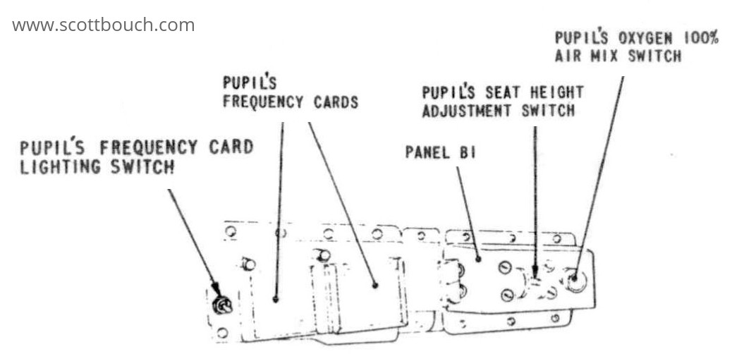
Panel B1
Location: Below coming on Port side.
Pupil's frequency card holders, are perspex slots to hold cards noting the 18 preset frequencies of the C1607/4 U/VHF control unit, and possibly for the ILS controller, but having never seen any of these cards I can't be 100% sure.
Not identified in the drawing is the rudder trim switch.
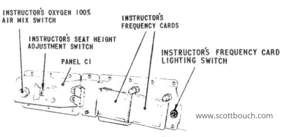
Panel C1
Location: Below coming on Starboard side.
Instructor's frequency card holders, etc.. description as above for Panel B1.
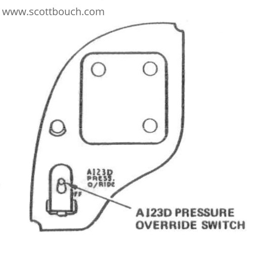
AI23D radar pressure override switch
Location: on left combing.
Also a hole for an ex-instrument, however I'm not sure what this would have been.
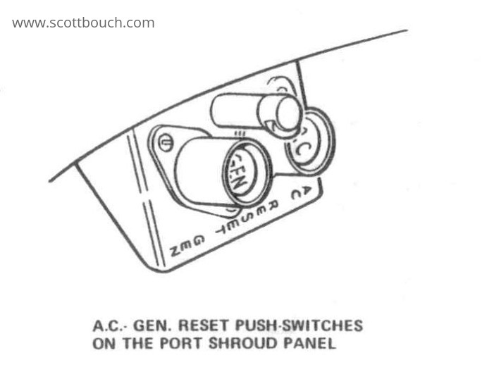
AC and DC Generator reset buttons
Location: on left combing.
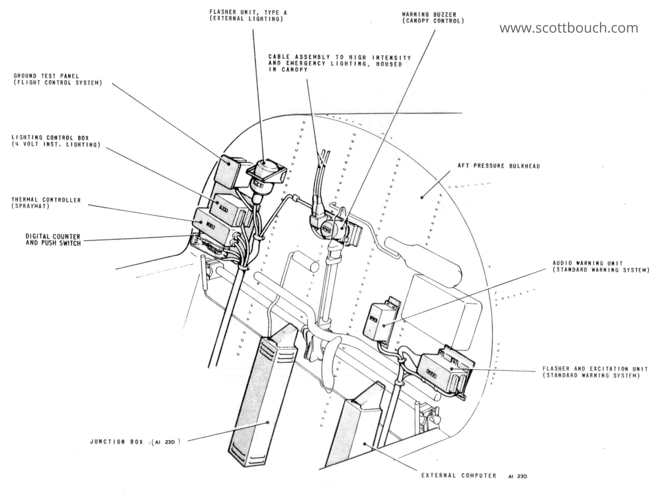
Rear Bulkhead
Cockpit aft pressure bulkhead equipment.
The Flasher Unit, type A (External Lighting), made by Specto Ltd, puts the spine and wingtip anti-collision lights into flashing mode, operating at about 2Hz, 1:1 mark space ratio.
The Warning Unit (Canopy Control) is a simple electro-magnetic buzzer made by Klaxon, and sounds whenever the canopy is raising or lowering.
The Audio Warning Unit (Standard Warning System) provides the "clangers" warning sound in the headsets whenever a warning light illuminates.
The Thermal Controller (Spraymat) controls the black heated "Spraymat" on the front of the radar struts in the air intake, used for anti-icing.
Cockpit access panels
Removable panels allowing access to wiring and mechanical linkages under the floor and in the side consoles
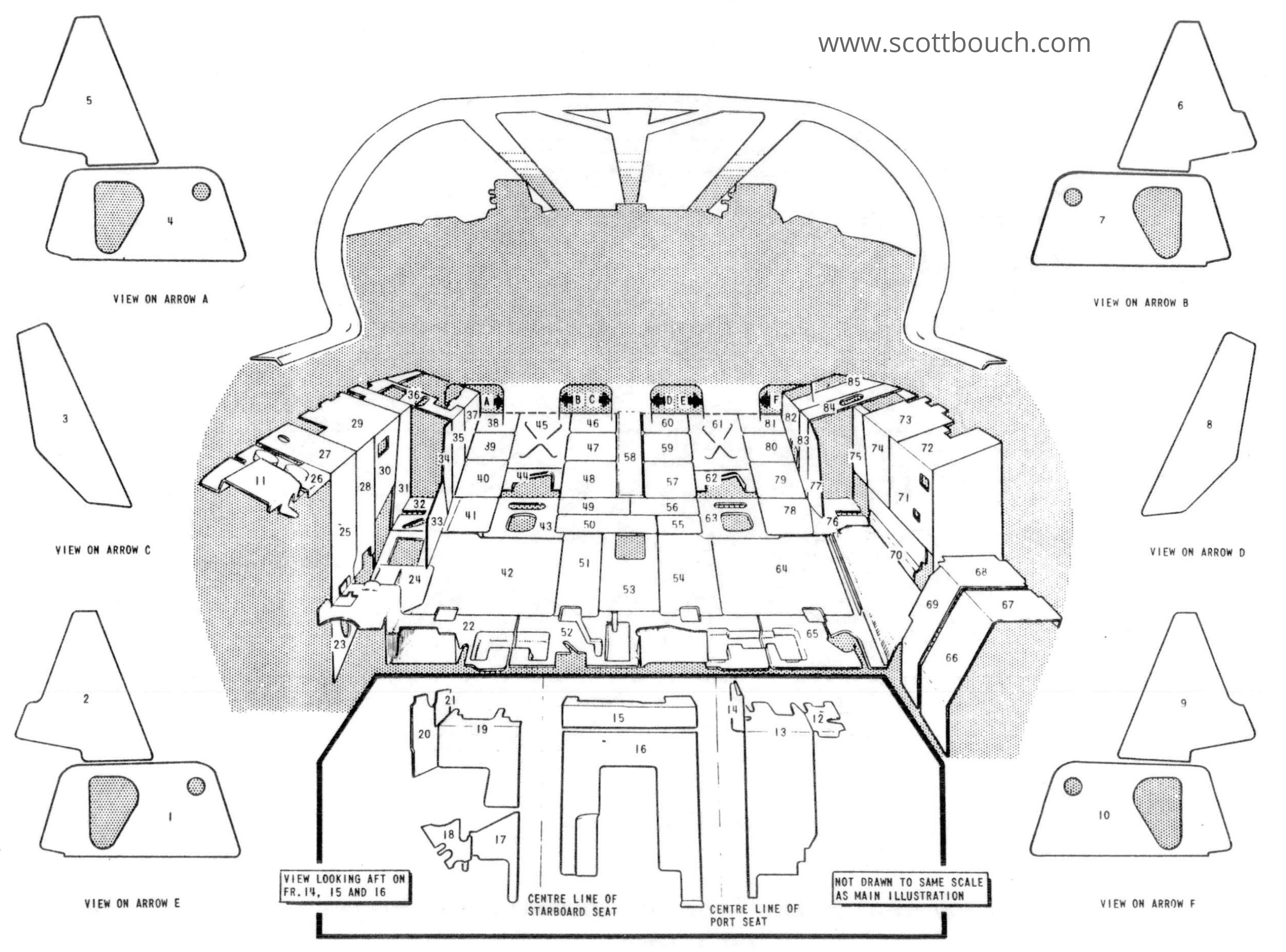
All extracts from AP-101B-1005 Vol 1.