Aircraft Cockpit Instrument Simulation
A friend recently inspired this project - he's an A320 pilot, and had been off work after breaking his shoulder snowboarding. To keep his skills up during recovery, he put together a simulator at home based on several computer monitors to display the instrument graphics.

This made me question if it's possible to use real, un-modified, aircraft instruments in a mock panel?
- Of course it would, but it will be a big learning curve!
I started off by researching flight simulator software, looking for ease of extracting data from it. I settled on Flightgear, as it's free, Linux friendly, and has a massive community supporting it.
Control hardware
I found some examples where people had achieved similar projects using Arduino boards to interface the I/O with the computer. I happened to have an Arduino Uno, so began learning by using this.
A lot of people have made their own instruments using RC servo motors, or gutted real instruments to install servos, but I'm a bit of a purist with this sort of stuff, so want to engineer around the existing instruments.
The Arduino Uno really is too small to build a decent simulator, but it's great to learn form. Ideally you'd use a Mega as it offers much more I/O count, or a series of smaller boards (perhaps ATTiny85 based on an I2C network).
First experiments
Simple moving coil indicators
I began by trying to simply drive some cold-war era gauges with the Arduino Uno board. I used a potentiometer as my data source, saving the headache of serial data communications for later!
I started off simply by using basic two-terminal moving coil gauges.
This video shows a little test routine I wrote for the Arduino which gives them a full scale sweep on start-up. This is not realistic to real aircraft, but nice for a sim.
I'm using two 5V PWM outputs from the Arduino Uno to drive these gauges, via series resistors. Both gauges have different FSD (Full Scale Deflection) currents, so resistors had to be selected on an individual basis to calibrate their FSD position to 5Vdc.
Here is the basic Arduino Uno sketch I used for this test.
Engine percent RPM / REV indicators (tachometers)
These gauges are a little tricky to operate, as they are a three phase device, powered by a three phase tacho generator bolted on the engine. The generator spins a motor in the indicator at a varying speed, proportional to the engine speed. The motor is magnetically coupled ("slipping clutch") to the pointer mechanism, which drives against a spring.
Ian from gasturbineworld.co.uk kindly informed me that he's measured the tacho generator voltage to be typically around 26Vac RMS between phases. Varying the frequency will control the indicator position, as the tacho-generator speed is directly related to engine RPM.

Extract from T5 Lightning airframe wiring diagrams
I have a few 3 phase instrumentation synchro servo transmitters (rescued from a skip) which can be used to generate 3 phases, so I used one of these as a test generator by spinning it using a power drill, as can be seen in the videos below. Then the challenge will be writing some Arduino code to utilise three PWM outputs to simulate the three phases.
De Haviland Dove RPM Indicator
So, I found I had an indicator form a De Haviland Dove aircraft, that works just the same way as the Jet Percent RPM indicators. Luckily I just happened to have the correct type 3 pin Plessey "Breeze" connector lying around, so I conencted up a synchro to a battery drill, and 5Vdc power supply, and it worked:
I found that this gauge responded to being driven with 2.5Vac RMS, so should be ok to be directly driven from 3 Arduino PWM outputs if the current demand isnt too high.
Cold War Jet RPM Indicator
I'd found a Percent RPM indicator, similar to what was used in most cold war jets including the Lightning and Vulcan etc.. so gave it a whirl with the same synchro, this time at a fixed speed in my garage pillar drill:
It needed a higher voltage than the Dove RPM indicator to operate, so I stepped up the excitation voltage from 5Vdc to 12Vdc (resulting in about 12Vac RMS between phases (ignore multimeter reading), and it worked nicely!
RPM Solid State Drive
Initially I tried to greatly simplify the simulation of these gauges at low cost by using a 3 phase brushless motor speed controller for radio controlled aircraft / cars, however it didn't work as the motor coil impedance is too high, and these controllers see it as a faulty motor (open circuit).
So, I have managed to write the arduino code to generate three phases, and an external circuit; a triple half H-Bridge with PNP / NPN bipolar transistors to control the motor coils. It gors up to 30% / 40% RPM, then the step changes get too big and it falls over, so I think there's some part of my software converting the signal form linerar to logarithmic behaviour.
Onward from the bipolar transistor interface, I had a go at building a MOSFET interface, but just managed to send it up in smoke, so more development is needed there!
Fixing a percent RPM indicator
A friend recently gave me one of these percent RPM tachometers, but the pointers were stuck... so it needed taking apart.
This repair demonstrated the diversity of this project as a gas blow-torch is required to melt the solder holding the back of the indicator in place! Project diary here
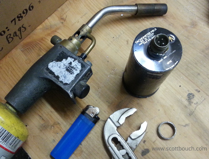
Once it's fixed, I'll have three percent RPM tachometers so could simulate the engines of a Tristar or Trident, but if I can find one more, I'll be able to simulate the V-Bombers!
Desynn Type Position Indicators
It's a three phase magnetic indicator, which would normally operate from Desynn transmitter...
A Desynn transmitter is a peculiar device in the history of analogue electronics. It's an endless potentiometer with three fixed connections, and two wipers to provide a DC current across the circular resistor. The two wipers move in relation to an aircraft surface like the flaps, or jet pipe nozzle position. The result is that the voltages on the three main connections vary like 3 phases would, in relation to the angle applied. There is a direct relation between applied angle to the movement of the signals.

Hawker Hunter Flap Position Indicator
I simulated a Desynn transmitter using 3 PWM outputs of an Arduino Uno, and code I wrote to look up the output values in a sine wave array spaces apart by 120 degrees. As with all things, it didn't work first time, but amazingly, one typo to correct and it worked like a charm!
The basic Arduino Uno sketch I used for this test.
It could be made smoother with a bit of y=mx+c interpolation between the data points in the array, or I could use an array with more points, whichever causes less load on the Arduino I guess will win.
Fuel contents indicators
A lot of cold-war fast jet aircraft used SMITHS GE-Series fuel contents gauges with the SMITHS Mk4 capacitive measuring system.

Smiths GE Series fuel contents indicator internal wiring
A steady 400Hz signal is provided to one motor coil, with the second coil receiving a 90 degree out of phase, variable voltage 400Hz signal. The motor is conencted to the needle mechanism via a slipping clutch. The instrument also includes a potentiometer connected to the needle for feedback to the amplifier circuitry, so accurate needle position can be calibrated.
Since the pointer of these indicators is moving against a spring, the motor only needs to turn in one direction, to oppose the spring. The motor will always need to rotate to hold the pointer still against the spring, the faster it rotates, the greater the pointer position, the slower the motor rotates, the lower the pointer position.
Pointer position feedback to the amplifier circuit is provided by the internal potentiometer, which allows closed loop control.
I still haven't got hold of ove of these to try, but am keeping my eye out.
3 pin, 2 coil indicators / ratiometer
This style of Weston indicator is used for pressures and temperatures, and possibly more applications. They are firtted with a 3 pin Cannon connector at the rear (some variants alternatively used screw terminals).
These indicators are supplied by 24V to the centre point of the two coils. A potentiometer is used to connect the coils to 0V (0V at the wiper). Varying the potentiometer reduces the current in one coil, while at the same time increases the current in the other coil, forcing the needle to move.
They are called a Ratiometer, as the needle position is the result of the ratio of the current in two coils. An alternative arrangement is with one coil permanently connected to +Vs (supply), and the other to a device ranging from 0V to +Vs. Both arrangements ensure the reading is never affected by fluctuations in supply voltage, improving reading accuracy over simple single coil indicators (such as those above).

Integration with Flightgear
Regarding finding a way to make the Flightgear software talk with the Arduino, you soon find out that there are many ways to skin a cat. Online there is no 'difinitive' way to do it, but a few snippets of other projects that people have created. Through this project, I'll try to document exactly what I've done, how and why.
I have managed to make a potentiometer Joystick send serial data to flightgear, and it works very well indeed, page here.
I received some great help from David Huddach in the USA during 2019, he figured out how to take data from FGFS over serial. Based on his work, I have had success in operating exhaust gas temperature, undercarriage position and fuel indicators from the FGUK Lightning model.
Flightgear to real jet pipe temperature indicator
Using a PWM output I was able to control this JPT indicator form FGFS. the Arduino DUE is powered from the Laptop USB socket, and has enough current source capability to operate this indicator; a nice simple experiment.
Flightgear to real undercarriage indicator
I temporarily fitted this real indicator with LEDs for this test as the Arduino board has enough current sourcing capability to drive them directly. To use the original bulbs a set of transistors is needed for teh current and voltage required.