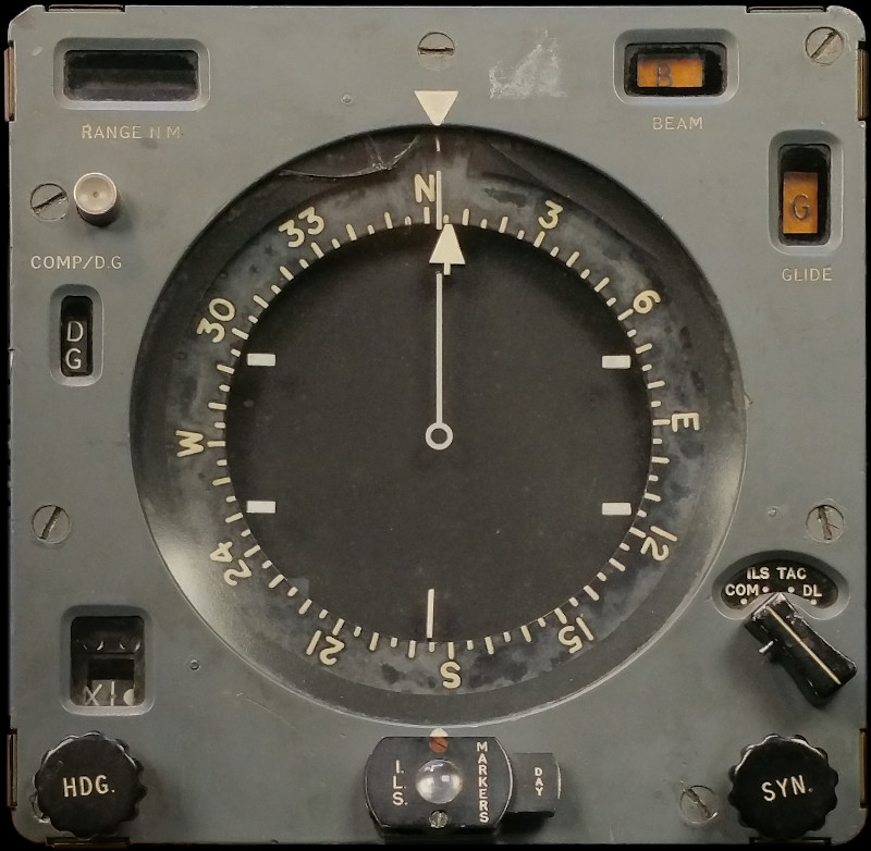
NAVIGATION DISPLAY MK. 1 TYPE C
LEADING PARTICULARS
| Stores Ref. No.: | 6TD/3650 |
| NATO Stock No.: | 6TD/6605-99-6204710 |
| Manufacturer: | Smiths |
| Attachment: | Crate |
| Connection: | Mc.Murdo red range |
DESCRIPTION
The navigation display provides the pilot with various parameters fed from several systems. It houses mechanisms and motors for operating the display, and relies upon a separate electronics unit, the navigation display amplifier, to control the motors.
The display has x4 modes of operation, which can be selected by the mode selector switch:
Mode: "COM" - Compass
No radio navigation information (i.e.: I.L.S. or TACAN) is presented in COM mode.
The compass card position is normally based on information from the MRG (Master Reference Gyro), here labelled as DG (Directional Gyro). If the MRG was to fail, the compass information source can be switched over to the Compass Detector mounted in the tail fin.
The MRG is used in preference to the compass detector as it responds quicker to changes. The MRG has the disadvantage though of precession which can cause the compass card to drift. Synchronisation between the MRG and the compass detector is indicated by the oscillating dot and cross indicator (above HDG knob), showing when the MRG needs to be re-synchronised with the compass detector. Re-synchronisation should be required every 10 minutes or so and is corrected in straight and level flight using the SYN knob.
Mode: "ILS" - Instrument Landing System
The instrument landing system presents localiser and glide path information using bars on the display. The localiser bars are presented by the roller blind, and glidepath by a single horizontal bar in front of the roller blind. The localiser bars can rotate and be laterally offset, representing the orientation of the glidepath relative to the aircraft, and lateral displacement of the aircraft from the localiser beam centreline.
The BEAM and GLIDE illuminated windows also indicate if the aircraft deviates from the path.

Navigation display in ILS mode
Displaying a centrally aligned runway
I.L.S. markers illuminate a blue/purple lamp in the indicator at the bottom middle. The lamp flashes at increasing frequencies as the markers are passed on approach. There is a selector for day/night which applies a dimming screen over the lamp.


Navigation display ILS marker lamp - day/night mode
The I.L.S. controls are located on panel A4 in the centre of the cockpit and present the pilot with a power switch, volume control, and type 705A control unit for channel selection which includes an ILS power indicator lamp.
Mode: "ILS" - for Violet Picture A.D.F. / U.H.F. Homing
With the I.L.S - Violet Picture switch set to Violet Picture, the ILS localiser bars are used to indicate a direction of a U.H.F radio transmission. Violet Picture was the name given to the UHF homing system, otherwise known as Automatic Direction Finding, or A.D.F. The C1607-4 V/UHF radio control unit mode selector switch needs to be set to ADF, and a suitable UHF frequency selected.
Mode: "TAC" - TACAN
The TACAN radio navigation system passes data to the navigation display to show a bearing and range (distance) to the TACAN homing point by means of concentric rings with bearing line. Additionally a separate counter (top left) indicates TACAN range. The homing point can be adjusted away from a TACAN beacon by use of the TACAN offset computer.
The TACAN system is controlled by the TACAN control unit, which presents controls for power, mode (air/air and air/ground), channel selection, and audio volume.

Navigation display in TACAN mode.
Displaying a homing point 140 NM away at a bearing of 30°
Mode: "DL" - Data Link or Direct TACAN
Data Link was intended to be a means of remotely sending flight command information to the aircraft via the UHF radio communication system. In practice, it was not fully developed and not fitted to service aircraft.
As the Data Link equipment was not fitted, the DL mode of this indicator is instead used for presentation of "Direct TACAN" information, ignoring any offset settings on the TACAN offset computer, and instead providing a bearing and range directly to the TACAN beacon. This eliminates any system errors/inaccuracies made possible by just setting the offset computer to 0 range and 0 bearing by cutting the offset computer out of circuit. This mode should also be used for Air-to-Air TACAN navigation, but only presents range information due to limitations of the airborne TACAN beacon equipment.
"SYN" knob
Used to synchronise the master reference gyro (MRG) to the compass detector. The compass and MRG are synchronised when the dot and cross indicator in the window above the HDG knob slowly oscillate left and right. When synchronisation is lost, the indicator shown either the cross or dot with no oscillation.
"HDG" knob
Adjusts the angle of the heading selection pointer. Discrepancies between the pointer selected heading and the aircraft heading are used by the flight director or the flight control system.
"COMP-DG" button
Switches between the compass detector (COMP) and the master reference gyro MRG (DG, Directional Gyro) as the source for compass information. A window below the button displays the currently selected mode.
CONSTRUCTION
A mechanical work of art, comparable to the inner workings of a delicate timepiece.
The navigation display mainly consists of gear trains, quadrature phase servomotors, and synchro transmitters/transformers. Some circuit boards for capacitors and resistors, and a few transformers and fuses.

Even the wiring looms demonstrate expert craftsmanship.


SIMULATION
Luckily I was given a copy of AP112B-0303 which gave enough detail to understand the complex workings of this unit, both mechanically and electrically.
If I can find a navigation display amplifier (see WANTED section below), operating this indicator will be a lot more straightforward, as it contains a lot of the motor drive circuitry.
WANTED
A Navigation Display Amplifier, either a type B, C or D will work fine for this application. These amplifiers were also used in other aircraft with the Smiths IFIS instrument system: Gnat T1, Buccaneer S1 and S2, and Hunter T7A configured for Buccaneer training.

Navigation display amplifier in the port elephant's ear of T Mk. 5 XS458, note how it is fitted upside down.
AP-112B-0303-1 provides the following stores ref. numbers (Note the amplifiers appear to have moved from stores section 6B to 6TD at some point):
| Amplifier unit | Ref. No. | |
|---|---|---|
| Type B | 6B/3243 | |
| Type C | 6TD/782 | |
| Type D | 6TD/1165 |

Navigation display amplifier image from AP112B-0303
| Mounting tray | Ref. No. |
|---|---|
| Type B | 6B/3022 |
Looking in the stores reference number vocabulary, AP1086 section 6TD, I have also found:
| Amplifier unit | Ref. No. | |
|---|---|---|
| Type B | 6TD/5 | |
| Type B | 6TD/782 |
But these numbers may just relate to the inner guts of the unit as the case and other parts are also listed out separately.
If you can help me to find one, please do get in touch.
REFERENCES
"IFIS" overview:
A.P.3456D, Part 2, Chap 3, A.L.14, May 1969 - Integrated Flight Instrument System - Paragraph 8
F Mk. 3, T Mk. 5 and F Mk. 6 aircrew manual:
A.P.101B-1003, 5 & 6A, Part 1, Chapter 7, A.L.2, Nov 1984 - Instruments - Paragraph 18
T Mk.5 electrical "Vol. 1":
A.P.101B, Sect.7, Chap.3C, A.L.67, May 1975 - Dynamic Flight Reference System - Paragraph 11
T Mk.5 electrical "Vol. 1":
A.P.101B-1005-1B, Sect.8, Chap.1, A.L.66, Sept. 1975 - U.H.F./V.H.F., Intercommunication and Telebriefing - Data Link paragraph 26, Violet Picture paragraph 29
Smiths literature:
Smiths Leaflet F2-2 - Flight Data System
EXTERNAL LINKS:
Wikipedia ↗ - Rainbow Codenames, Violet